Oil & Gas Journal, 95:43, 10/27/1997
Alexander Aynbinder
Fluor Daniel Inc.
Houston
A new method has been developed for determining stresses and pipe ovality that may result from external and internal pressures as well as from the stiffness of a composite steel-concrete wall.
The method also determines allowable external pressure for concrete-coated pipe to withstand collapse. Determining the effect of concrete coating on the allowable external pressure may allow reduction of pipe W.T. of, in some cases, up to 50%.
The proposed method is based on buckling (collapse) criteria for pipe to be laid in deep water and utilizes a standard calculation procedure for bare steel pipe that accounts for the stiffness of the composite wall.
The issue of pipe collapse from external hydrostatic pressure is very important for a pipeline laid in deep water, specifically for a large-diameter pipeline. Frequently, the design W.T. of an offshore pipeline is governed by local buckling criteria rather than hoop stress criteria.
Pipe concrete coating for an offshore pipeline is traditionally used to increase the pipeline's specific gravity.
The concrete coating thickness mainly depends on pipe OD and W.T. For a pipe with an OD/W.T. ratio of 60 and for a concrete density of 140 lb/cu ft, the ratio of required concrete-coating thickness to pipe W.T. is approximately 9.3 to achieve a pipe specific gravity of 1.2.
British Standard for Design of Pipelines Subsea states that "any beneficial effect of weight coating on buckling should not be taken into account in analysis unless satisfactory analytical and experimental evidence is provided."1 Such analytical evidence is provided here.
Also, numerical data of collapse pressure are defined. This definition is based on the classical strength of material methods, considering the nonlinear property of concrete, and the principle and methodology of existing codes with some conservative assumptions.
The complicated problem of buckle propagation is outside the present scope. The propagation pressure depends on the buckle (collapse) initiation pressure; the suggested method, therefore, would be useful for gauging the effect of the concrete coating on pipeline buckle propagation pressure.
Concrete-coated pipe is the composite section that consists of bare steel pipe and concrete, usually reinforced by cages. In investigations of the behavior of this composite section, the nonlinear property of concrete is considered, i.e., nonlinear stress-strain relationship.
The steel is considered to have linear behavior because the hoop stress, as a result of external and internal pressures, usually does not exceed the steel limit proportionality between stress and strains.
The iterative method2 is used for consideration of concrete elastic-plastic behavior. The stiffness is modified after each step of calculations on the basis of a secant modulus. The total load, or pressure, is applied in each iteration and the calculation process is repeated until the displacements converge.
Although the nonlinear stress-strain relationship is used to compute the secant modulus in each iteration, it is important to note that each-stiffness is utilized as if it described a linear elastic body.
In a sense, therefore, each step is equivalent to an elastic analysis. No separate consideration of elastic and plastic stresses and strain is necessary in this method. The computed secant modu* for each iteration are treated as if they were elastic constants.
As a result of external and internal pressures on a pipe annulus, the equation3 from static condition of equilibrium is that found in Equation 1 (accompanying equations box).
This solution in terms of radial and hoop stresses is found in Equation 2.
Because we assume that steel (as well as concrete) is linear for each iteration of calculation, these two equations may be used for both materials with constants for certain materials: steel, Es, µs; concrete, Ec, µc. As mentioned before, the concrete constants are calculated on each step of calculation.
Then, for solution, four constants of integration (Xi) needed to be determined. These constants may be determined from the boundary condition: the radial stresses on internal (r = ri) and external (r = rc) surface equal to internal and external pressure, respectively, and on the boundary between steel and concrete (r = ro), the radial stresses and radial deflections are equal (Equation 3).
This boundary condition yields a system of four linear algebraic equations, which can be written in the general form of Equation 4. The coefficients of the matrix are in Equation 5; right-hand sides, Equation 6.
By substituting the value of constants (Xi) determined from Equation 4 in Equations 2, the stress distribution across the wall may be found for each iteration for known elastic parameters E and µ.
To calculate effective elastic parameters for concrete (steel being assumed linear), a nonlinear model of concrete is used. Based on engineering traditions and methodology of ACI Code4 that the first part of the stress-strain curve is linear, the proposed stress-strain diagram is divided in to three sections:
The equations of concrete model (stress-strain relationship) are found in Equations 7 and 8. These are applied for compressive and tensile strength. Even though the tensile strength of concrete is small, it allows a general solution to be obtained and reinforcing cages to be considered. These equations use the following symbols:
Ec,o = Concrete modulus of elasticity by ACI code
f' = Concrete compressive or tensile strength
f'c = Compressive strength
f't = Tensile strength
ey = Strain required to produce maximum compressive or tensile strength
eyc = Compressive strain
eyt = Tensile strain
eu = Maximum usable concrete compressive or tensile strain
euc = Compressive strain
eut = Tensile strain.
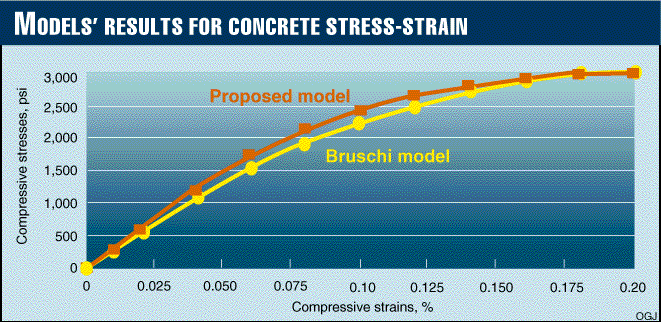
Bruschi presents a single equation to describe a compressive
stress-strain diagram in a strain interval from 0 to 2%.5 
Comparison (Fig. 1 ) shows that both concrete models, Bruschi's and the proposed here, give very close results. For design purposes, the proposed model may be preferred as corresponding more closely to the methodology of ACI code.
For engineering purposes, the proposed model's spreadsheet was developed to obtain a numerical solution according to the previously described method and equations. The concrete secant modulus for each step is based only on the average hoop stress in the wall of concrete, the radial stress was neglected, and the nonlinear concrete model described by Equations 7 and 8 was used.
The concrete effective modulus of elasticity (Ec) is equal to the secant modulus on last iteration, and the equation calculating the effective Poisson's ratio is shown in Equation 9.
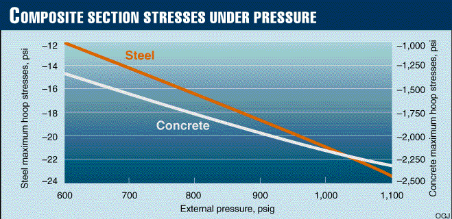
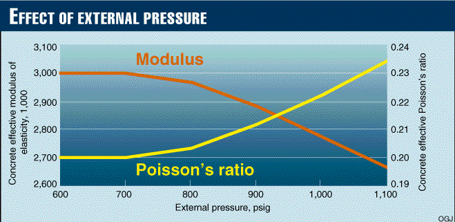
Data presented in Fig. 2 [62,466 bytes] and Fig. 3 [62,737 bytes] were obtained for concrete-coated pipe 24 in. OD x 0.409 in. W.T. with thickness of concrete coating equal to 3.7 in. The concrete modulus of elasticity and Poisson's ratio were taken as 3,000 ksi and 0.2, respectively.
For this example, the maximum hoop stresses in the concrete are approximately 10 times less than in steel. The concrete effective modulus of elasticity is reduced by 13% and Poisson's ratio increases by 15% if the external pressure increases to 1,100 psig from 700 psig.
Stresses, deflections, and strains for two values of external pressure are presented in example calculations. (See the accompanying box.)
The stresses and deflection may be used for evaluation criteria of stresses and ovality. The concrete effective modulus of elasticity and the effective Poisson's ratio will be used for collapse analyses.
The critical external pressure for a perfect (without any reduction for tolerance) thin-walled annulus from elastic material is proportional to the flexural rigidity.6
The Codes1 7 give a more-complicated solution for calculating the collapse external pressure for bare steel pipe, considering the inelastic behavior of steel, as well as the initial ovalization of the pipe cross section according to BS 8010.1
These equations may be used for a composite section with known flexural rigidity.
For determining the flexural rigidity of a cross section of concrete-coated pipe wall, the engineering method suggested by Timoshenko3 will be used for a section made of two different materials with different moduli of elasticity.
Assuming that there is no sliding between the steel and concrete during bending, then, according to the theory of solid beams, the elongation and contraction of the longitudinal fibers are proportional to the distance from a neutral axis.
In this case, the cross section of concrete-coated pipe may be modeled by a steel transformed T-section with a web thickness proportional to the ratio (n) of the modulus of elasticity of concrete (Ec) to the modulus of elasticity of steel (Es).
To account for cracking, creeps, and other specifics, a reduction factor (Cc) is included in the theoretical determination of web thickness (Equation 10).
The distances from the center mass of steel and center mass of concrete to the neutral axis of the transformed section may be calculated by Equation 10.
The moment of inertia per unit length of the composite section transformed transferred to the steel with respect to the neutral axis is found in Equation 11.
Another engineering method4 8 for determining the position of a neutral axis assumes that concrete-coated pipe is concrete reinforced by bare steel pipe.
The position of the neutral axis (distance from an outside surface of concrete) can be located by equating the components of the internal couple (Equations 12 and 13).
Then the distances from the center of mass of steel and from center of mass of concrete to a neutral axis may be calculated by Equation 14.
The moment of inertia per unit length of the composite section transferred to the steel with respect to the neutral axis is calculated by Equation 15.
For this case, a reduction factor (Cc) is also included to account for cracking, creeps, and other specifics, as stated earlier.
The values of K1 and K2 in Equations 11 and 15 represent the increasing flexural rigidity of concrete-coated pipe vs. bare steel pipe. The comparison of the values is presented in Fig. 4 [60,537 bytes].
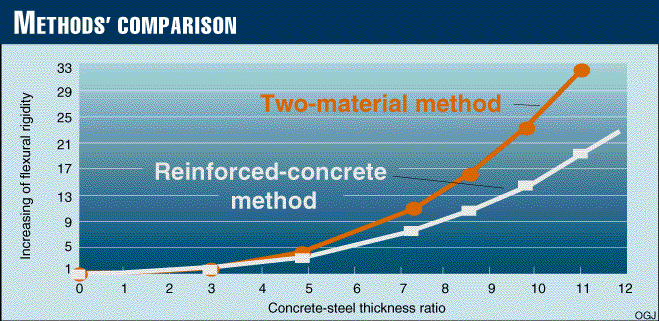
These curves are calculated for steel pipe with a 24-in. OD and 0.409-in. W.T., a concrete-steel modular ratio n = 0.1, and a concrete reduction factor value equal to 0.05.
The second, reinforced method gives a more-conservative result and in the absence of experimental data should be preferred.
As noted earlier, the concrete effective modulus of elasticity depends on concrete hoop stress, and the influence of the nonlinear property of concrete on composite section flexural rigidity is presented in Fig. 5 [55,654 bytes].
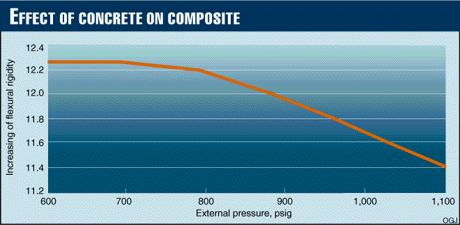
The parameters of increasing the flexural rigidity of concrete-coated pipe vs. bare-steel pipe allow the buckling-critical external pressure to be determined for a composite section based on the solution for bare steel pipe.
Equations 16-19, the final equations for design, are based on the method presented in API RP 1111.
The value of K (Equation 17) depends on the concrete-reduction factor. This factor, because of the methodology of the ACI code for calculating flexural rigidity of the cross section of a column,4 may be assumed equal to 0.1.
For concrete-coated pipe, this reduction factor may need to be reduced in part because in the annulus perimeter, the steel is in a compressive zone. During the first phases, because of an absence of experimental data, the conservative value Cc = 0.05 may be assumed for design purposes.
Also as a conservative solution, the radius in Equations 16 and 17 is assumed to be equal to the outside radius of concrete rc.
The results of the collapse-pressure determination for two types of concrete-coated pipe, based on the suggested method per API RP 1111, are presented in the example calculations.
Equations 16 and 17 may also be used to determine the external pressure required to cause the collapse of concrete-coated pipe based on an equation, according to the British Standard for bare steel pipe (Equation 20).1
The proposed method makes it possible to determine stresses, displacements, and strains in the concrete-coated pipe that result from external and/or internal pressures and to determine collapse external pressure based on the method presented in API RP 1111 and/or BS 8010.
The method also uses the methodology of ACI code, concrete elastic-plastic behavior, and conservative assumptions to account for the specifics of concrete.
The effect of considering concrete coating against collapse pressure is to reduce steel pipe W.T., and therefore the cost of pipeline.
Table 1 [37,568 bytes] presents examples of pipe with a 24-in. outside diameter. The allowable operating (internal) pressure for this pipe from hoop stress criteria is 1,470 psig, if the steel grade is X-60 and hoop stress design factor is 0.72.
The results of calculations, represented in Table 1, show that using the suggested method, pipe with the steel W.T. designed to withstand internal pressure, and the concrete coating thickness that meets buoyancy criteria, the allowable depth of water under offshore pipe may be increased approximately four times.
The last example in this table shows how to determine steel W.T. at designated values of water depth and thickness of concrete coating using the suggested method.
An analytical solution is obtained with the assumptions that are, for the most part, conservative.
The experimental data will allow the value of concrete-reduction factor for accounting reinforcing cages, actual cracking, creeps, and other specifics of concrete and its interaction with steel pipe to be increased.
Application of the suggested method with less conservative assumptions will require more experimental data to provide evidence of so large a beneficial effect of concrete coating on buckling.

Alexander Aynbinder is a senior project engineer at Fluor Daniel Co., Houston. Previously, he was in the civil engineering department of Gulf Interstate Engineering. Before emigrating to the U.S. in 1990, Aynbinder was a lead research scientist in the Russian State Research Institute for Pipeline Construction. He is a graduate of the Moscow Civil Engineering Institute and received a PhD in civil engineering from the Central Research Institute of Civil Structures, Moscow. Aynbinder is a member of ASME.
Copyright 1997 Oil & Gas Journal. All Rights Reserved.